

.png)

Seven Critical Surfaces That Must Remain Uncoated on Data Center Power Equipment
Powder coating is used throughout data center infrastructure to provide a durable, consistent finish on cabinets, electrical enclosures, power distribution equipment, switchgear housings, UPS equipment, structural frames, brackets, panels, and other fabricated metal components.
But a successful powder coating process isn't simply about achieving complete coverage.
In many applications, complete coverage would actually create a problem.
Electrical contacts need to conduct. Grounding and bonding locations need reliable metal-to-metal contact. Threads have to accept hardware. Gaskets need properly controlled sealing surfaces. Components still have to fit together after the finish is applied.
That means manufacturers and contract powder coaters have to control not only where powder goes, but also exactly where it doesn't go.
On data center power equipment, a no-coat area is often a functional part of the component—not simply an unfinished spot.
Although every drawing and application is different, the following seven surface types deserve particular attention when developing a masking and racking process for powder-coated data center power equipment.
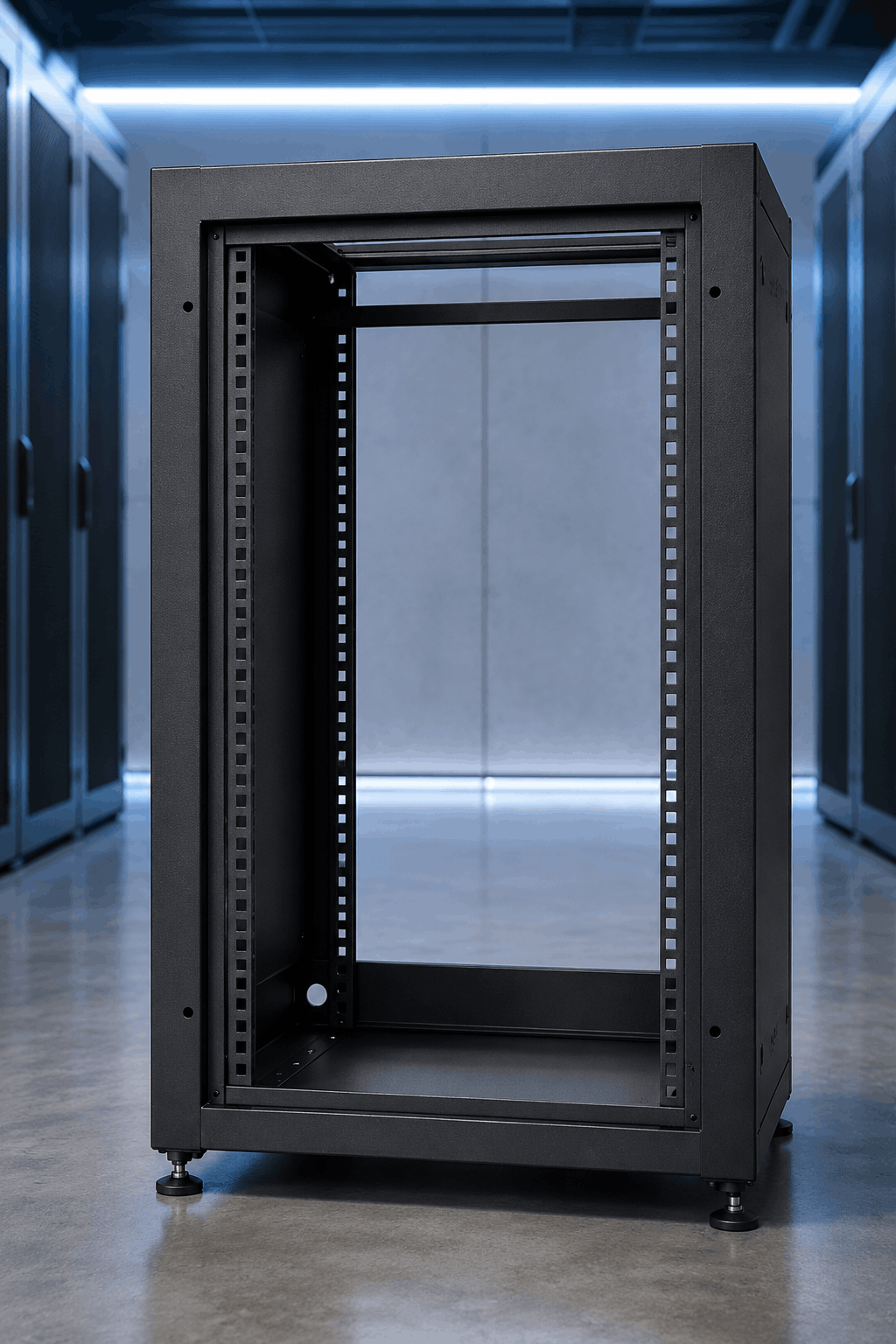
1. Grounding & Bonding Points
Grounding and bonding surfaces are among the most important no-coat areas on electrical equipment.
Powder coating creates a durable protective finish, but that finish is generally electrically insulating. If powder covers a location intended to provide conductive metal-to-metal contact, electrical continuity can be compromised.
Data center power equipment may contain designated grounding pads, bonding locations, chassis contact points, mounting locations, studs, or other interfaces that need to remain free of coating according to the equipment design.
The challenge is that these areas are not always large or visually obvious. A relatively small grounding pad can be surrounded by a much larger surface that requires full coating coverage. The masking process therefore has to create a repeatable boundary while protecting the precise area specified by the drawing.
Depending on geometry and production volume, this may involve high-temperature masking tape, die-cut masks, caps, plugs, or custom masking designed around the grounding feature.
The hanging method also matters. In electrostatic powder coating, reliable rack-to-part contact is necessary for the coating process itself. A rack contact point covered with excessive coating buildup can introduce its own grounding problems even when the component's permanent grounding surfaces are masked correctly.
For that reason, product grounding and process grounding should both be considered when developing the finishing method.

2. Electrical Contact Surfaces
Not every conductive surface is technically a grounding point. Data center power systems also contain electrical interfaces whose function depends on controlled contact between conductive components.
Busbars are an obvious example. Depending on the design, a busbar or related electrical component may contain a combination of bare, plated, insulated, or otherwise treated surfaces. Contact areas used for electrical connections need to meet the requirements specified for that assembly.
Allowing powder coating to bridge into a designated electrical contact area can interfere with the intended interface. At the same time, masking too much of the component can expose surfaces that were supposed to receive protective finishing.
This makes edge definition especially important.
For repeated geometries, operators may be tempted to measure and cut tape manually for every component. That can work, but it also introduces operator variation. One person may place the tape slightly differently from another. Boundaries may shift from batch to batch, and trimming adds touch time.
When the same contact geometry is masked repeatedly, pre-cut die-cuts or custom masking can help standardize masking placement and reduce manual measuring and trimming.
3. Threaded Holes, Studs & Fastener Interfaces
Threads are easy to overlook because they occupy relatively little surface area. But a small amount of unwanted coating in the wrong threaded feature can create a disproportionately large production problem.
Powder inside an internally threaded hole can interfere with fastener engagement. Powder on an externally threaded stud can create similar assembly difficulties. Operators may then have to chase threads, remove coating manually, replace hardware, or send the component through another rework step.
Multiply that extra work across dozens of threaded locations and hundreds of components, and a small masking issue becomes a significant labor problem.
Common protection methods include:
- High-temperature masking plugs for threaded holes
- Threaded or tapered plugs for specific opening geometries
- High-temperature caps for studs and projections
- Custom molded masking for complex or repeated features
The correct solution depends on more than the nominal hole diameter. Mask selection should account for insertion depth, thread geometry, cure temperature, pretreatment chemistry, desired masking boundary, installation speed, and removal.
A plug that technically fits but is difficult to install or remove may not be the best solution for a high-volume production line.
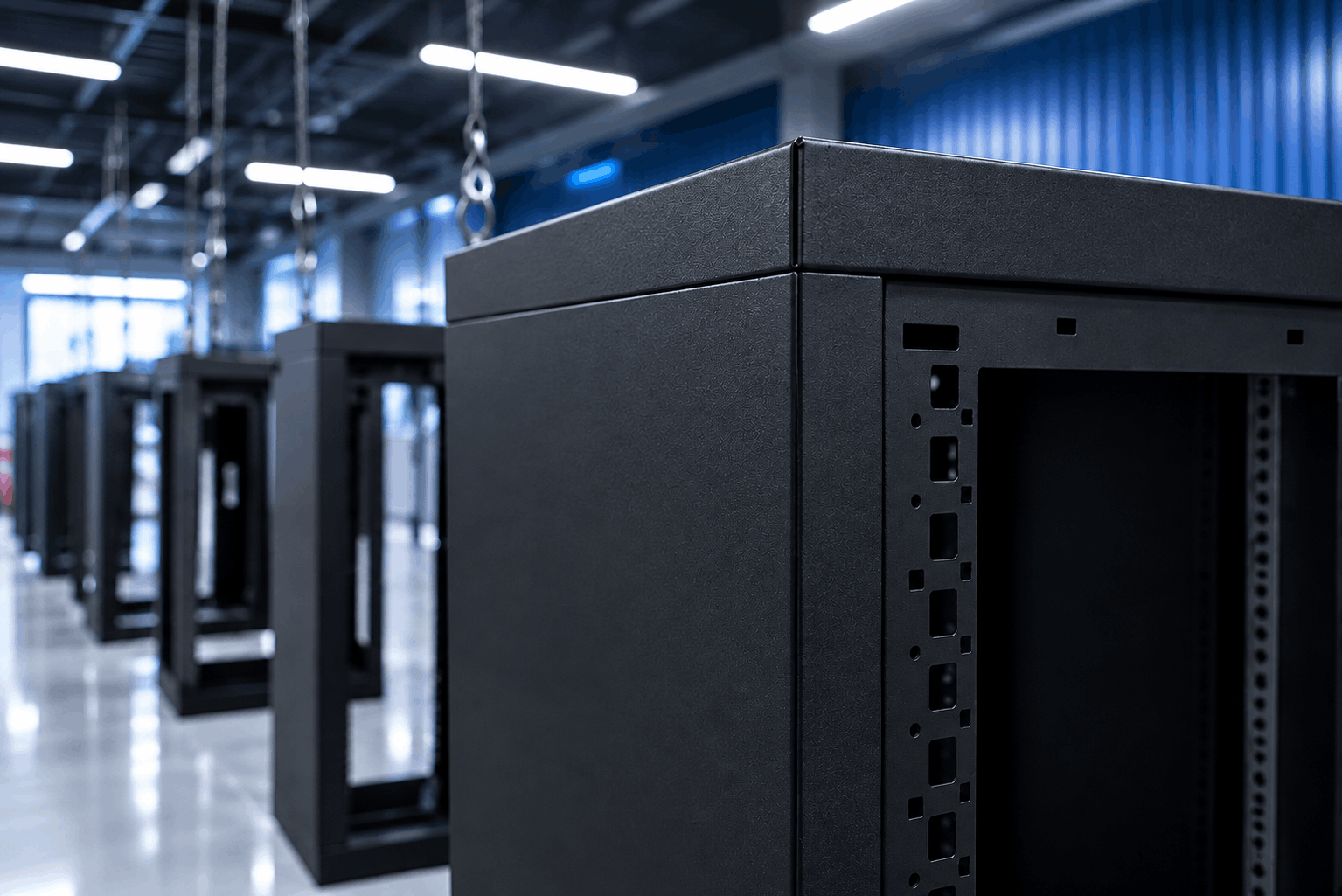
4. Mating & Assembly Surfaces
Powder-coated components rarely operate alone. Cabinets, enclosures, power equipment, frames, panels, brackets, rails, doors, and structural members eventually have to be assembled with other components.
Some of the surfaces involved in those connections may need to remain free of coating.
A mating interface can have requirements related to electrical continuity, dimensional fit, mechanical alignment, hardware seating, or another assembly function. Even when the coating thickness seems small, applying finish to both sides of a tightly controlled interface can change the final fit.
This is why masking decisions should be made from the finished assembly requirements—not simply by looking at an isolated part before coating.
When reviewing a component drawing, ask:
- What attaches to this surface later?
- Does the interface require metal-to-metal contact?
- Is there a controlled dimensional relationship?
- Will hardware need to sit flush against this area?
- Could coating buildup affect alignment or assembly?
These questions can identify no-coat areas that might otherwise be missed during finishing process development.

5. Gasket Lands & Sealing Surfaces
Sealing surfaces introduce a different type of no-coat requirement.
Data center power and cooling infrastructure can include doors, access panels, electrical enclosures, fittings, manifolds, liquid-cooling equipment, and other assemblies that rely on gaskets or seals.
Where a gasket must seat against a controlled surface, unwanted coating may alter the interface. Depending on the design, the concern could involve surface condition, dimensional buildup, sealing pressure, or the consistency of the sealing boundary.
These applications require particularly careful review because the correct masking strategy depends on the actual sealing design. The goal is not simply to assume every gasket surface should be bare; it is to protect the specific surface condition required by the engineering drawing and qualified process.
For repeat production, the masking boundary should also be easy for operators to reproduce. Hand-cutting complicated gasket profiles with tape can consume substantial masking labor and introduce variation.
Pre-cut masking shapes or custom molded masks may provide a more repeatable alternative when the geometry and production volume justify them.
6. Ports, Bores & Functional Openings
Power equipment and adjacent data center systems contain numerous openings that serve a functional purpose after finishing.
These can include cable-entry features, mounting holes, fittings, connector locations, internal bores, ventilation features, access openings, and—in liquid-cooling equipment—fluid ports and passages.
Not every opening needs to be completely free of powder. But when the internal diameter, thread, sealing surface, connection point, or downstream cleanliness requirement matters, uncontrolled coating intrusion can create problems.
This is another area where simply covering the face of the opening may not be enough.
The required mask depth should be defined. Does only the front edge need protection? Does the entire bore need to remain clean? Is there an internal thread? Is a fitting inserted to a specific depth later? Where exactly should the coating boundary stop?
Answering those questions before choosing the masking product can prevent both under-masking and unnecessary over-masking.
Good masking starts with defining the functional boundary—not with choosing a cap or plug from a catalog.
7. Precision & Dimensional Interfaces
Finally, some surfaces must remain uncoated simply because the component has to maintain a controlled dimension.
Powder coating adds material to the substrate. In many areas, that added thickness is expected and beneficial. At a close-tolerance interface, however, coating buildup may change the final relationship between components.
Examples can include locating features, precision mounting points, hardware seats, slots, alignment surfaces, bearing or bushing interfaces, close-fitting tabs, and other controlled geometries.
The exact tolerance requirements will vary significantly by component, so the engineering drawing should always define what must be protected.
These areas can also be among the easiest to miss because they may not look like conventional masking locations. A threaded hole obviously suggests that something will be inserted into it. A flat machined pad or narrow edge may not be as visually obvious to a finishing operator.
Clear work instructions, repeatable masking products, fixtures, and visual standards can help translate engineering requirements into a process operators can reproduce consistently.
The Real Challenge: Protecting the Right Area Every Time
Identifying a no-coat surface is only the first step.
The larger manufacturing challenge is protecting that same surface correctly across every part, every operator, every shift, and every production run.
A masking method that works perfectly on one prototype may become inefficient when applied to 500 parts. A manually cut piece of tape may meet the drawing, but if it requires repeated measuring and trimming, labor can quickly exceed the cost of the masking material itself.
Manufacturers should evaluate the complete masking process, including:
- Mask installation time
- Placement repeatability
- Pretreatment and chemical exposure
- Powder-coat cure temperature and dwell time
- Masking edge definition
- Ease of removal after cure
- Potential for coating leakage
- Mask reuse where applicable
- Cleanup and rework
- Operator training and process consistency
The cheapest masking product per piece is not necessarily the lowest-cost masking process per finished component.
.png)
Masking and Racking Should Be Engineered Together
Masking gets much of the attention when discussing no-coat surfaces, but racking can be equally important to the final result.
The rack determines where the part is supported, how it is oriented, where electrical contact occurs during powder coating, how much access the spray equipment has to the component, and how efficiently operators can load and unload the line.
A poorly chosen hanging point can interfere with a masked area. A contact location that accumulates coating can reduce electrical continuity. A rack that allows parts to move can cause masks to shift or components to contact one another.
For data center cabinets, power-equipment panels, structural frames, brackets, and fabricated assemblies, the best process considers masking, grounding, hanging, part presentation, coating access, and demasking as one system.
How EPSI Can Help
Data center power equipment can contain dozens—or even hundreds—of features that have different finishing requirements. EPSI works with manufacturers and contract finishers to develop masking and racking solutions around the actual component, finishing process, production volume, and functional requirements.
That can mean selecting a standard plug for a threaded opening, developing a die-cut for a repeatable grounding pad, engineering a custom molded mask for a complex component, or designing racking that improves grounding and part presentation through the powder-coating line.

Caps, Plugs, Tapes & Discs
Protect threads, studs, grounding points, contacts, openings, and other defined no-coat surfaces with masking selected around geometry and process conditions.
Explore Masking
Custom Masking
Replace repetitive tape-and-trim work or multi-piece masking setups with an application-specific solution engineered around the component.
Explore Custom
Custom Racking
Engineer part support, conductive contact, orientation, spacing, coating access, and line density around the needs of your specific component.
Explore Racking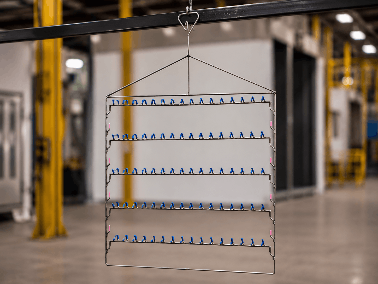
Modular Racking
Reconfigure hanging layouts as part families and production requirements change without creating a dedicated welded rack for every application.
Explore Modular RackingStart With the Function, Then Choose the Mask
The most important question in industrial masking isn't, “Which plug or tape should we use?”
It is, “What does this surface need to do after finishing?”
Once that is clear, the masking method can be built backward from the functional requirement.
For data center power equipment, that may mean maintaining electrical continuity at a grounding point, keeping powder out of a threaded hole, preserving a contact surface, protecting a gasket land, maintaining a precision fit, or controlling exactly where coating ends at an assembly interface.
When those requirements are identified early and translated into a repeatable masking and racking process, manufacturers can reduce unnecessary rework while making the finishing operation easier for operators to execute consistently.
The goal isn't simply to keep powder off certain areas.
It's to make sure every surface still does its job after the powder coat cures.
Frequently Asked Questions
Why do some surfaces need to remain uncoated during powder coating?
Some surfaces perform electrical, mechanical, sealing, or dimensional functions that coating could interfere with. Examples include grounding points, electrical contacts, threads, gasket surfaces, mating areas, and precision interfaces. The component drawing and qualified finishing process should define the required no-coat areas.
How does pretreatment affect masking selection for data center hardware?
Masking products may be exposed to more than the powder-coat oven. Depending on the finishing line, data center components can encounter cleaning solutions, rinses, conversion coatings, spray pressure, and other pretreatment conditions before powder is applied. A mask that tolerates the cure temperature still needs to remain secure and functional throughout the complete finishing process. Mask selection should therefore consider pretreatment chemistry and exposure as well as cure temperature and dwell time.
Can powder coating interfere with electrical grounding?
Powder coating is generally electrically insulating, so designated grounding or bonding surfaces may need to remain free of coating to maintain the metal-to-metal contact required by the equipment design. Proper rack-to-part contact is also important during electrostatic powder application.
How should manufacturers validate a new masking process for data center components?
A new masking method should be evaluated under the actual production conditions it will encounter, including pretreatment, handling, powder application, cure temperature and dwell time, cooling, and mask removal. Finished components should then be inspected against the applicable drawing and customer requirements. Depending on the application, qualification may also include electrical continuity, grounding, sealing, dimensional, or final assembly testing.
How do you protect threaded holes during powder coating?
High-temperature masking plugs are commonly used to protect internal threads, while caps can protect studs and external features. The appropriate product depends on the thread or opening geometry, masking depth, cure temperature, pretreatment chemistry, installation requirements, and desired coating boundary.
What causes powder coating to leak underneath a mask?
Powder intrusion can result from poor mask fit, incorrect sizing, inconsistent installation, inadequate sealing at an edge, part geometry, or a mask shifting during processing. Repeated leakage at the same location may indicate that the masking method itself should be reevaluated. A different standard mask, die-cut shape, or custom solution may create a more repeatable no-coat boundary.
What is the best way to mask grounding points?
The best method depends on the size, shape, location, process conditions, and production volume. High-temperature tape, discs, die-cuts, plugs, caps, and custom masking may all be appropriate. For repeat production, a standardized mask can improve placement consistency compared with repeatedly measuring and trimming material by hand.
When should a data center equipment manufacturer move from hand masking to a standardized masking method?
Hand-cut tape can be practical for prototypes, low-volume production, and frequently changing geometries. As production volume increases, however, repeated measuring, cutting, positioning, trimming, and removal can become significant sources of labor and variation. If operators repeatedly create the same mask by hand, it may be worth evaluating pre-cut tape shapes, standard caps or plugs, reusable masks, or custom molded masking.
Can coating thickness affect component assembly?
Yes. At close-tolerance mating or dimensional interfaces, coating buildup can affect fit, alignment, hardware seating, or other assembly requirements. Engineering drawings should identify surfaces where coating thickness cannot be accommodated.
What should contract powder coaters request from data center equipment manufacturers before quoting a job?
Useful information includes current drawings, clearly identified no-coat areas, coating specifications, critical dimensions, grounding or contact requirements, expected production volumes, and any customer-specific inspection or testing requirements. Understanding recurring production volume is also important because the most economical masking method for a prototype or short run may be very different from the best method for ongoing production.
When does custom masking make sense?
Custom masking can make sense when standard products require multiple pieces, extensive hand trimming, inconsistent placement, difficult removal, or excessive operator time. Production volume, labor savings, quality requirements, and mask reuse should all be considered when comparing custom and standard solutions.
How should no-coat areas be inspected after powder coating?
Inspection should be based on the functional requirements of the component rather than simply whether the masked area looks clean. Depending on the application, manufacturers may need to verify masking boundaries, absence of unwanted coating, thread functionality, dimensional requirements, electrical continuity, grounding performance, sealing performance, or final assembly fit. Critical acceptance requirements should be defined in the work instructions or quality plan before production begins.
Does racking affect no-coat areas during powder coating?
Yes. Racking determines part support, orientation, conductive contact, spacing, and coating access. Hanging points and rack geometry should be considered alongside masking so that the rack does not interfere with protected surfaces and maintains reliable contact throughout the finishing process.
Need Help Protecting Critical No-Coat Surfaces?
Bring EPSI your part geometry, drawing, no-coat requirements, finishing process, and production volume. We can help evaluate standard masking, custom solutions, and racking around the application.