

.png)
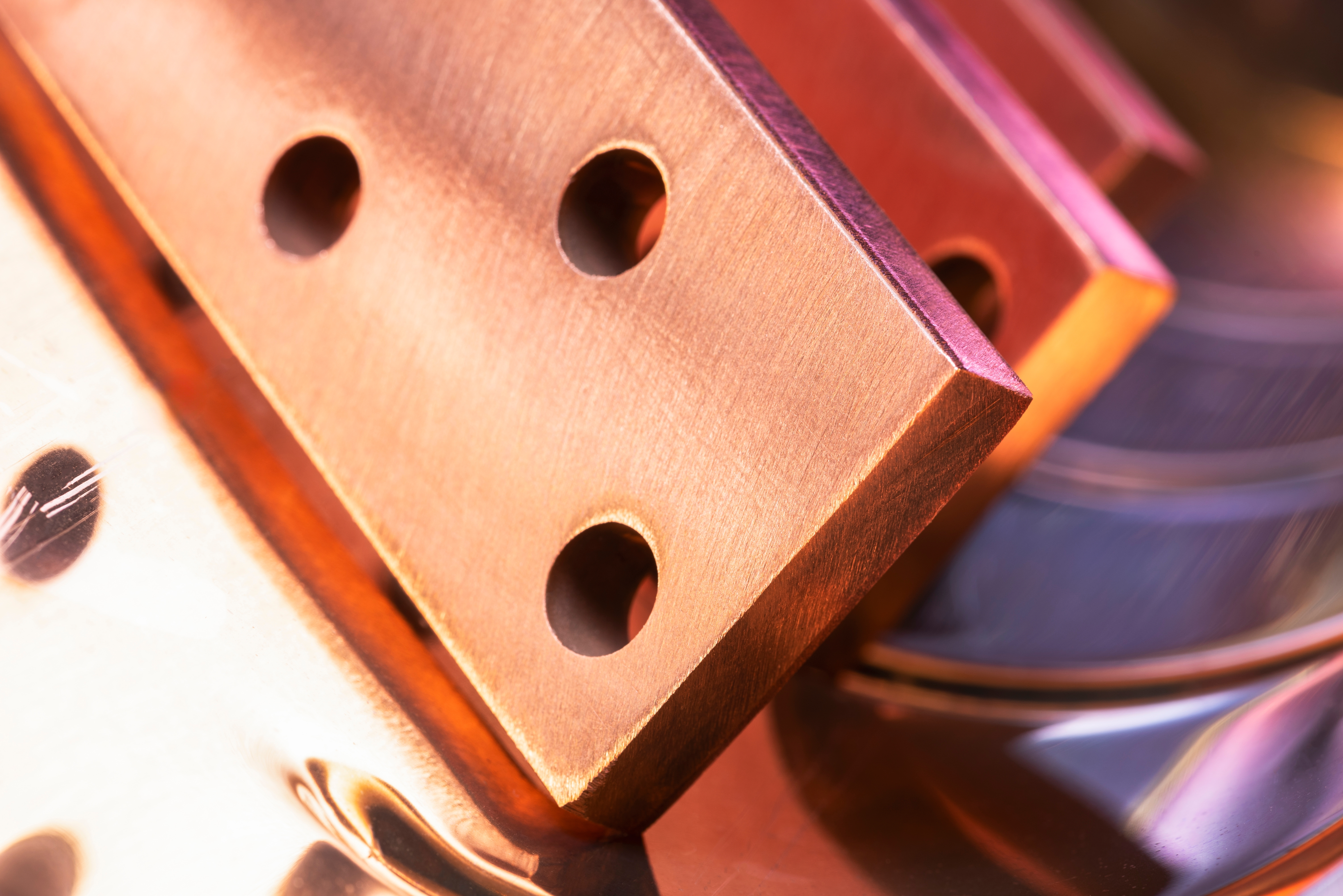
How to Protect Busbar Contact Areas During Plating and Powder Coating
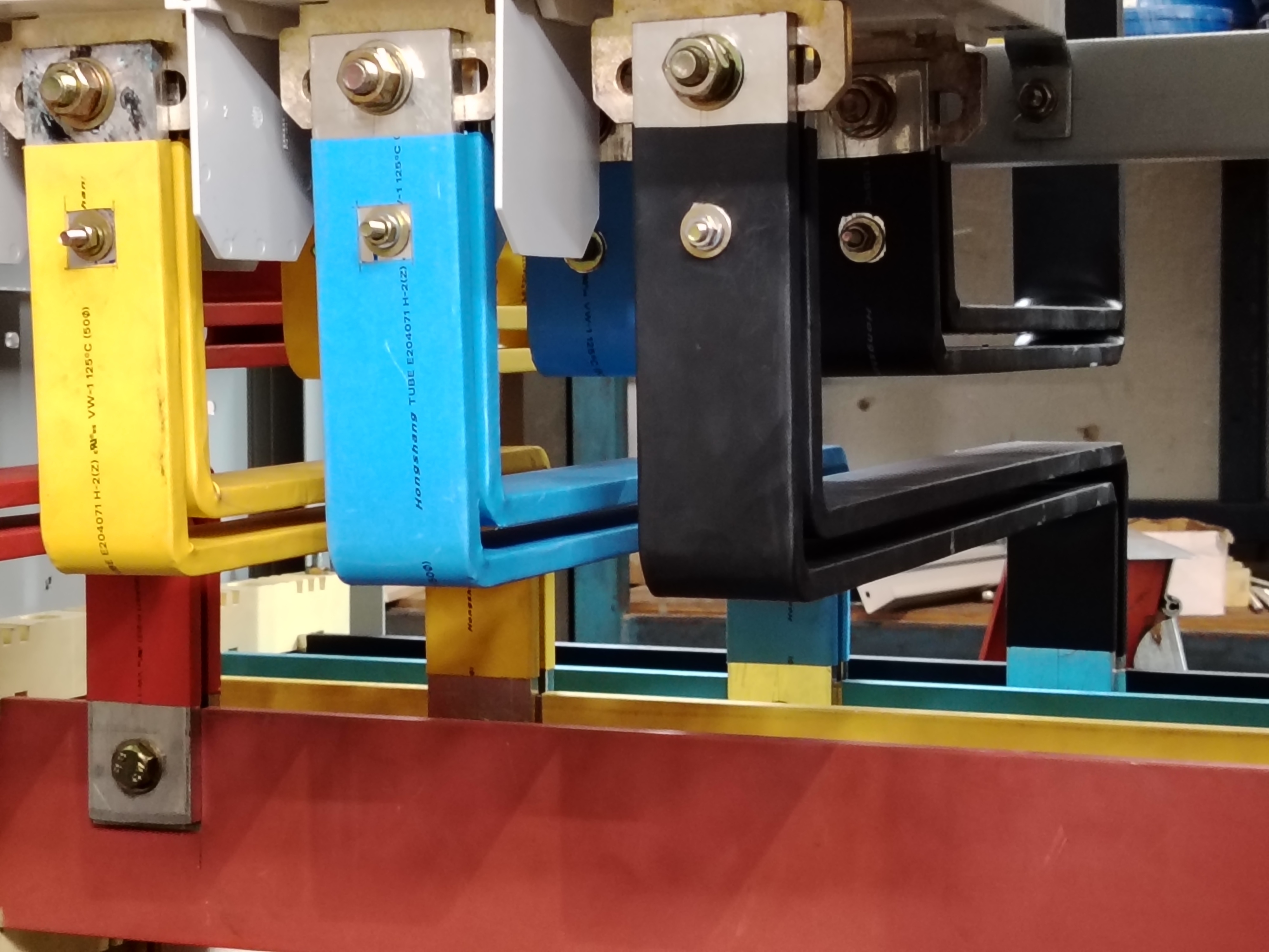
Busbars sit at the center of many high-current power-distribution systems used in data centers, switchgear, UPS equipment, PDUs, power shelves, control cabinets, and other electrical assemblies.
From a finishing standpoint, however, a busbar is rarely just one uniform surface.
One area may need a plated finish. Another may need to remain free of powder coating. A bolted connection may depend on a controlled contact surface. A nearby section may require protective coating or insulation. Holes, hardware locations, grounding interfaces, and dimensional features may each have their own finishing requirements.
That makes busbar masking less about simply “covering part of the copper” and more about controlling where one surface condition ends and another begins.
The first question is not “What should we mask?” It is “What finished surface does the drawing require in each functional zone?”
That distinction matters because a contact surface is not automatically supposed to remain bare. Depending on the engineering specification, a connection area may be bare copper, plated, or treated in another defined way. The masking process must preserve the specified finished condition—not substitute a generic no-coat rule for the component design.
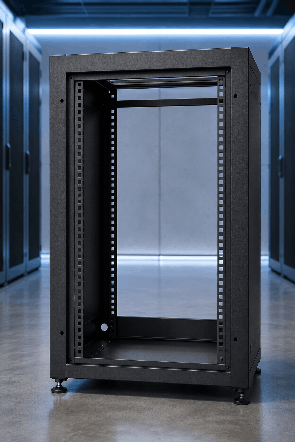
A Busbar Can Have Several Different Surface Requirements
A fabricated busbar may look simple compared with a cabinet or enclosure, but its surface-finish map can be significantly more complicated.
Depending on the design, a single component may include:
The correct finishing plan starts by identifying these zones from the drawing, specification, or qualified manufacturing process.
That is especially important when more than one finishing operation is involved. A busbar may move through cleaning, plating, rinsing, masking, powder coating, curing, demasking, assembly, and final inspection. A mask that works for one step may not necessarily be appropriate for the entire sequence.
Start by Defining the Contact Area Precisely
One of the most common sources of inconsistency is an imprecise definition of where the protected area should begin and end.
“Keep powder off the contact” sounds clear until an operator has to decide exactly how far the mask should extend.
Should the masked zone follow the edge of a bolt pattern? Extend beyond a washer footprint? Match a machined feature? Stop at a specified dimension from the end of the bar?
If the boundary matters functionally, it should not depend on an operator estimating it visually from part to part.
For recurring production, manufacturers should translate the engineering requirement into something that can be installed consistently. That may involve a dimensioned work instruction, placement fixture, die-cut mask, pre-sized tape format, or custom molded mask that naturally locates against the part geometry.
The goal is to reduce interpretation at the finishing line.
Plating Masking and Powder-Coating Masking Are Not the Same Problem
Plating and powder coating may both require selective masking, but the mask can encounter very different process conditions.
During plating, the protected area may be exposed to cleaning stages, aqueous chemistry, rinses, electrical current, process solutions, and repeated immersion or spray conditions. During powder coating, the mask may need to tolerate pretreatment, dry-off, electrostatic powder application, elevated cure temperature, and removal after the coating has flowed and cured.
A material selected because it survives a powder-coat oven should not automatically be assumed suitable for a plating process. Likewise, a masking method used successfully in plating may not produce the required edge, removal characteristics, or thermal performance during powder coating.
For every process, evaluate:
- Process chemistry and exposure time
- Temperature and dwell time
- Mask adhesion or mechanical fit
- Required boundary tolerance
- Potential leakage or solution intrusion
- Ease of installation
- Removal after processing
- Residue or cleanup requirements
- Whether the mask is disposable or reusable
The material is only one part of the decision. Geometry and operator method can be just as important.
The Finishing Sequence Changes the Masking Strategy
There is no single universal sequence for finishing every busbar design.
Depending on the component and specification, plating may occur before another coating operation, selective finishing may be performed in separate stages, or different regions of the part may require different protection throughout the routing.
That means the masking plan should be developed around the actual manufacturing sequence rather than treating each finishing operation in isolation.
Ask questions such as:
- Which finished surface must exist before the next operation begins?
- Does a previously finished area need protection from the next process?
- Will the same mask remain on the component through multiple stages?
- Could a mask trap chemistry, rinse water, or contamination?
- Will the mask survive later heating or handling?
- When is the safest and fastest point to remove it?
These questions can reveal why a masking method that appears efficient for one station creates unnecessary work somewhere else in the process.
Powder Coating Can Create Problems at Electrical Interfaces
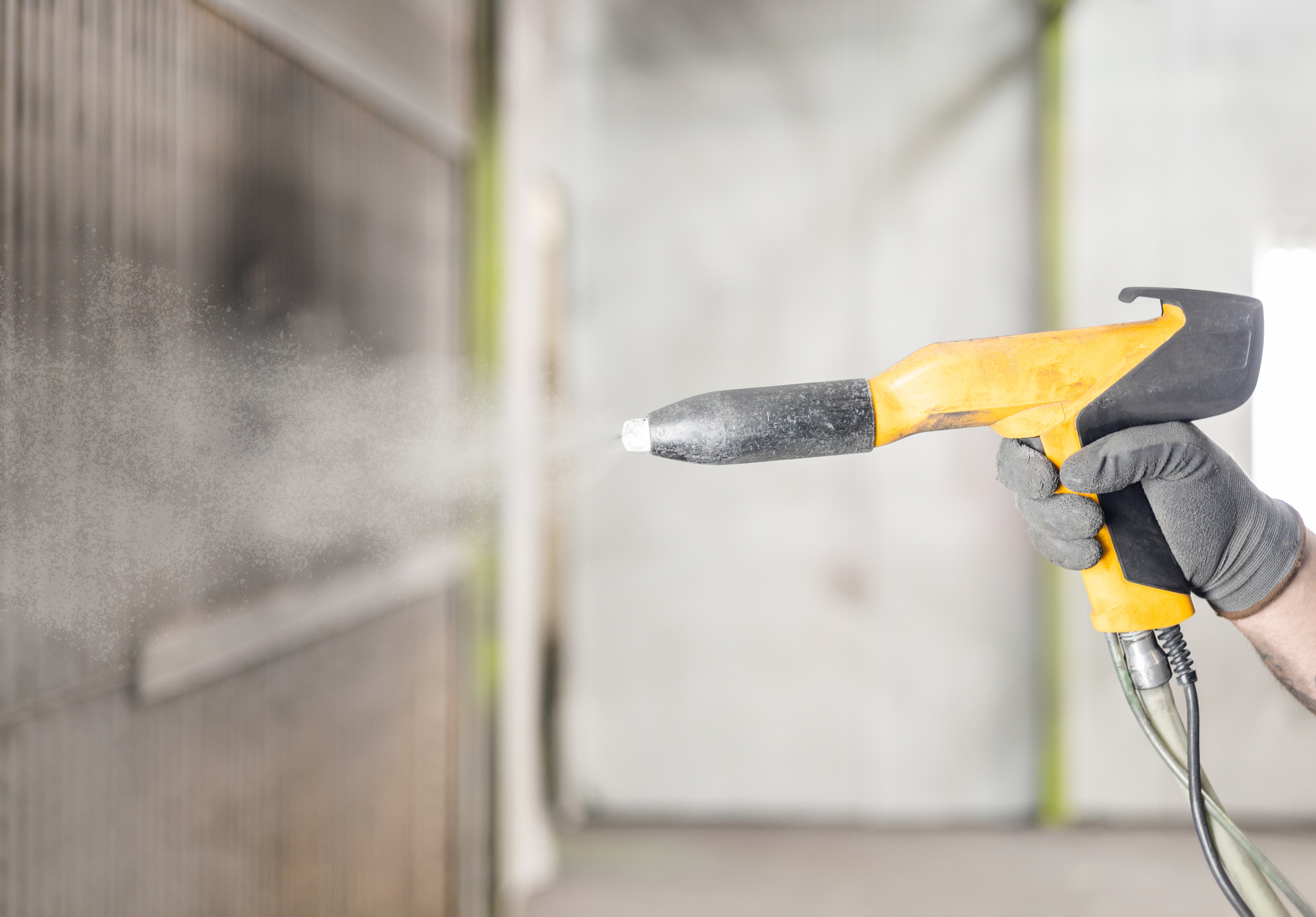
Powder coating is used extensively on cabinets, enclosures, frames, power equipment, and related hardware because it provides a durable and consistent finish.
But powder coating is generally electrically insulating.
If it extends into a contact zone that was intended to provide a controlled conductive interface, the finished assembly may no longer match the design requirement.
That is why overspray and edge creep matter even when the majority of the contact pad remains clean.
A masking boundary needs to remain secure through application and cure so the final transition occurs where expected. If the mask lifts, shifts, or allows powder underneath the edge, operators may have to scrape, sand, chemically remove, or otherwise rework the contact area after finishing.
That corrective work adds labor and can make final results less consistent.
A few seconds spent improving mask placement can prevent minutes of coating removal, inspection, and rework later.
Sharp Boundaries Become More Important as Volume Increases
At prototype volume, an experienced operator may be able to measure and cut masking tape individually for each busbar.
That approach becomes harder to justify when the same geometry is processed hundreds or thousands of times.
Repeated manual masking can include:
- Measuring the protected area
- Cutting tape to length
- Aligning it to a feature
- Trimming around holes or corners
- Burnishing the edges
- Inspecting placement
- Removing multiple pieces after finishing
- Cleaning up inconsistent boundaries
Every individual step may be short, but the combined touch time can become substantial.
When the geometry repeats, pre-cut die-cuts, shaped masks, reusable molded pieces, or locating fixtures can reduce both application time and operator-to-operator variation.
This is where cost-per-part matters more than mask unit price.
A custom solution may cost more initially than a strip of tape, but that comparison is incomplete if the tape requires repeated measuring, cutting, trimming, and cleanup on every part.
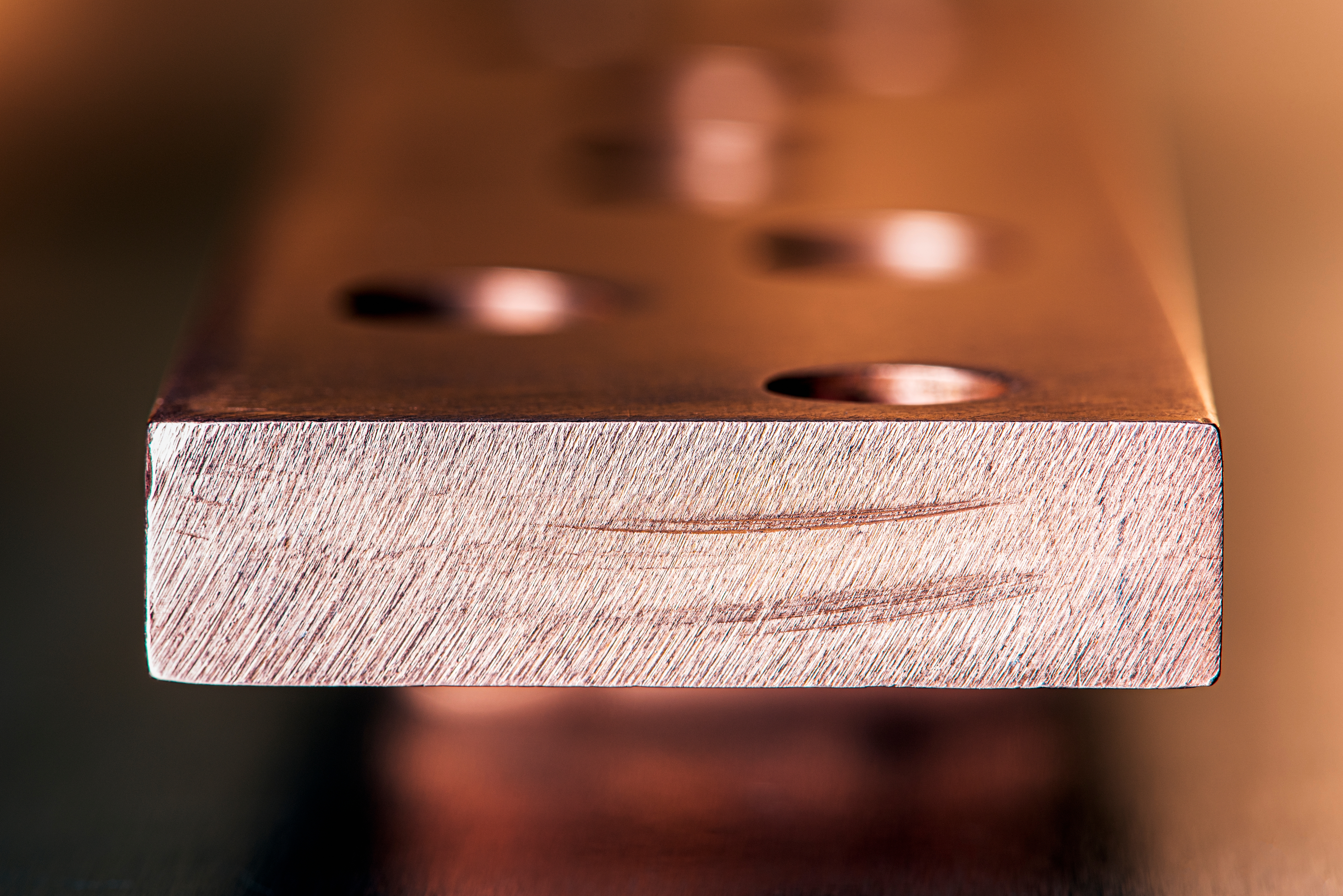
Holes, Slots, Threads and Hardware Locations Need Their Own Review
The contact face is not the only surface that may need protection.
Busbars and associated power-distribution components may include mounting holes, slots, threaded features, studs, hardware interfaces, locating features, or other areas with defined finishing requirements.
In some applications, the face around a hole may require one finish while the inside diameter requires another. A fastener interface may need a controlled contact area even though the surrounding surface is coated.
That can make a single flat piece of masking inadequate.
Instead, the best approach may combine a die-cut surface mask with plugs, caps, or another feature-specific solution.
For higher-volume applications, a custom mask may be able to protect several nearby features in one installation rather than requiring operators to apply multiple individual products.
A Clean Masking Edge Is Only Part of the Quality Requirement
After finishing, it is easy to judge a mask solely by appearance: the edge looks straight, the contact pad looks exposed, and the coating seems to have stayed where it belongs.
But visual inspection may be only one part of acceptance.
The finished component may also have requirements related to:
- Contact-zone dimensions
- Plating coverage and thickness
- Powder-coating thickness
- Surface cleanliness
- Electrical continuity
- Joint resistance or other customer-defined electrical tests
- Hardware fit
- Flatness or dimensional requirements
- Adhesion or coating quality
Those acceptance requirements should be defined by the applicable drawing, specification, customer requirement, and qualified manufacturing process.
Masking should support those requirements—it should not attempt to define them.
Contract Finishers Need More Than a Highlighted Drawing
Busbar programs are often processed by outside platers, powder coaters, or other contract finishers.
For those suppliers, quoting and running the job efficiently depends on receiving enough information to reproduce the manufacturer's intended finished condition.
Useful inputs can include:
- Current part drawings and revision levels
- Clearly dimensioned masking boundaries
- Which areas are bare, plated, coated, or otherwise treated
- Plating and coating specifications
- Critical holes, threads, contact pads, and hardware areas
- Masking-boundary tolerances where applicable
- Expected production quantities and frequency
- Required inspection or test criteria
That information also helps determine whether a simple manual masking method is sufficient or whether the economics favor a more standardized solution.
Standardization Matters When Several Busbar Part Numbers Share the Same Features
Data center power equipment manufacturers may produce many related busbar geometries across different power shelves, PDUs, switchgear assemblies, UPS systems, and other platforms.
Instead of treating each part number as a completely separate masking problem, look for recurring feature families.
Several parts may share:
- The same contact-pad dimensions
- Common bolt-hole patterns
- Repeated hole diameters
- Similar end geometries
- Common plated lengths
- The same grounding or mounting interfaces
Standardized masking around those features can reduce the number of masking products operators need to identify, stock, and learn.
It can also make work instructions easier to maintain as programs scale.
.png)
Racking and Contact Location Still Matter
Masking protects the finished interface, but the way the component is held through processing can affect the overall finishing result.
For powder coating, rack-to-part contact is especially important because the electrostatic coating process relies on a conductive path through the part and hanging system.
Contact location, rack cleanliness, coating buildup, part orientation, and movement can all affect process consistency.
For plating, fixturing and electrical contact requirements may be different and should be developed around the specific plating process.
In either case, the fixture should not interfere with the finished contact zone or create unnecessary downstream cleanup.
The best process considers masking and fixturing together rather than solving one and discovering later that it conflicts with the other.
How EPSI Can Help
Busbar masking can range from a simple strip of high-temperature tape to a multi-feature custom solution designed around plating boundaries, powder-coat keep-out zones, holes, hardware locations, and recurring contact geometries.
EPSI works with manufacturers and contract finishers to evaluate the complete application—including geometry, process chemistry, cure temperature, production volume, operator touch time, removal, repeatability, and downstream requirements.
The objective is not automatically to replace every standard mask with a custom product. It is to identify the most practical way to produce the required finished surface consistently and efficiently.

Caps, Plugs, Tapes & Discs
Protect threads, studs, contact areas, holes, openings, and other defined finishing boundaries with masking selected around geometry and process conditions.
Explore Masking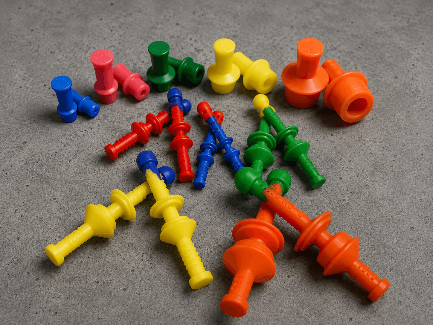
Custom Masking
Replace repeated tape cutting, trimming, and multi-piece setups with an application-specific solution engineered around recurring busbar or power-equipment geometry.
Explore Custom
Custom Racking
Engineer part support, conductive contact, orientation, spacing, coating access, and line density around the requirements of the component and finishing process.
Explore Racking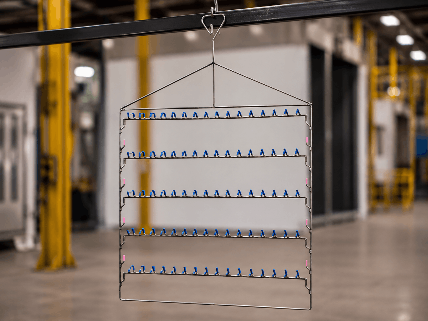
Modular Racking
Reconfigure hanging layouts as part families change without creating a dedicated welded rack for every component or production program.
Explore Modular RackingThe Best Masking Process Starts With the Finished Connection
Busbar masking should never begin with the assumption that every electrical contact needs the same treatment.
Start with the required finished interface.
Determine which surfaces must be plated, which must remain free of powder coating, which may be coated, where boundaries must fall, what downstream assembly requires, and how the completed part will be inspected.
Then select the masking method that can reproduce those conditions through the actual manufacturing process.
For low-volume work, that may still be carefully applied tape and standard masking products. For repetitive production, the better answer may be die-cut masking, reusable molded components, fixtures, or a custom solution that removes several manual steps.
The goal is not simply to keep coating off a busbar. It is to preserve the exact surface condition the electrical connection was designed to use.
Frequently Asked Questions
Should busbar contact areas always remain bare?
No. A busbar contact area may be bare, plated, or otherwise finished depending on the engineering specification. The correct masking process should preserve the required finished condition shown on the drawing or defined by the qualified manufacturing process rather than assuming every electrical connection should expose bare copper.
Can the same masking material be used for both plating and powder coating?
Sometimes, but suitability should be evaluated against each process. Plating can expose masking to cleaning and plating chemistries, rinsing, immersion, or spray conditions, while powder coating may involve pretreatment, dry-off, electrostatic application, and elevated cure temperatures. Material compatibility, sealing performance, removal, residue, and the required masking boundary should all be considered.
What causes inconsistent masking boundaries on busbars?
Common causes include manually measuring each part, inconsistent tape placement, poor alignment to part features, mask movement, inadequate edge sealing, dimensional variation, or unclear work instructions. Repetitive applications may benefit from die-cut masking, locating features, fixtures, or custom masks that make the correct placement easier to reproduce.
When should a busbar manufacturer consider die-cut masking instead of hand-cut tape?
Die-cut masking becomes worth evaluating when operators repeatedly measure and trim the same contact geometry, when masking boundaries need better repeatability, or when production volume makes manual preparation a significant source of labor. The comparison should include application time, trimming, removal, scrap, rework, and operator consistency—not only material cost.
How should busbar masking be inspected after finishing?
Inspection should follow the applicable drawing and quality requirements. Depending on the component, this may include checking the location and dimensions of the masking boundary, plating or coating coverage, surface cleanliness, holes or hardware interfaces, dimensional fit, and any customer-defined electrical or mechanical testing required for the finished assembly.
Can custom masking protect several busbar features at once?
Yes. When several holes, contact areas, edges, or other protected features occur in a repeatable geometry, an application-specific mask may be designed to combine multiple masking steps. Whether that approach is economical depends on part geometry, production volume, mask life, installation time, removal, and the labor required by the current method.
Does the order of plating and powder coating affect masking?
Yes. The manufacturing sequence determines which finished surfaces must be protected during subsequent operations and what conditions the mask must survive. The correct sequence varies by component and specification, so masking should be developed around the actual process routing rather than assuming one universal order for all busbar applications.
What information should a contract finisher receive for a busbar masking job?
Useful information includes the current drawing and revision, clearly defined plated, coated, bare, and protected zones, masking dimensions or tolerances, applicable finish specifications, critical holes and hardware areas, expected production volume, and required inspection or testing criteria. Clear requirements help the finisher select a masking method that can be repeated consistently.
How can busbar masking be standardized across multiple part numbers?
Look for recurring feature families such as common contact-pad sizes, bolt patterns, hole diameters, end geometries, or plated lengths. Standardizing masks around shared features can simplify work instructions, operator training, inventory, and replenishment while still allowing part-specific solutions where the geometry requires them.
Need Help Standardizing Busbar Masking?
Bring EPSI your part drawing, contact-area requirements, finishing sequence, current masking method, process conditions, and production volume. We can help compare standard masking, die-cut options, custom solutions, and racking around the application.